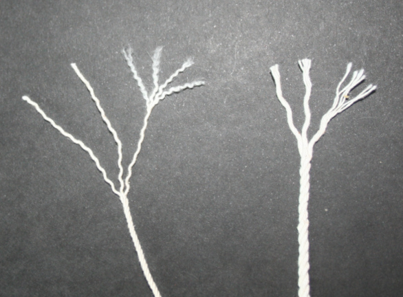
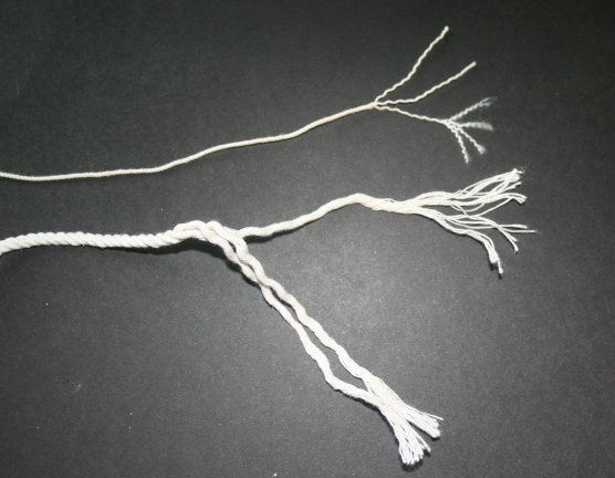
Here's a photo of number 72 twine similarly untwisted into its
yarns. Each strand has 24 yarns.
It is important to note that the direction that the plies are
twisted together is opposite to the direction that the yarns were
twisted together to make the individal strand to ply. In this case, the
yarns are twisted together in a "cable lay" direction to make each ply
and then three plies are twisted together in a "rope lay" direction
to make the final twine. The initial twist of fibres in the yarn itself in
this case was "rope laid". There is more discussion of these terms
for direction of rotation of the twist just below.
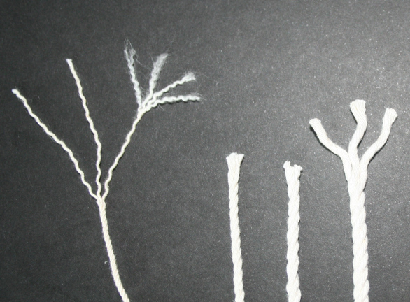
The second picture shows an assortment of seine twines, numbers 12,
18, 24, and 72. Because of the way it is made, with three plies containing
equal numbers of yarns, seine twine will always have a designating number
that is a multiple of three. Also, as seine twine gets larger and the
component plies contain greater numbers of yarn, the individual
plies tend to get softer, as the larger numbers of yarns are progressively
more difficult to spin tightly. Commercial suppliers sell seine twine up to
size 164 although the largest sizes commonly available are 90 and 120.
Cotton seine twine made today is spun from relatively short staple cotton
and tends to be softer than twine made in the early 20th century from the
longer (2.5 inch) staple Sea Island Cotton, which is no longer available.
If I wanted to make a rope for ship modeling that was the equivalent size of
larger seine twines (72 and up), I would make it up by spinning and plying
in multiple steps so the final product was made up not from many strands of
yarns but from a cable made from ropes made from the yarns. The multiple
steps will produce a much more tightly spun and better plied rope than
one made from large numbers of yarns directly. Something to remember that
will be revisited below.
In the weaving world, much attention is paid to the direction
in which a yarn has been twisted. That is largely because when
fabric is woven, the yarns of the weft lie across the yarns of
the warp. When two yarns cross each other, they tend to
"nestle" together, with the degree of fit determined
by the direction of twist of each yarn. Yarns of the same
twist direction to not nestle much when crossing at perpendiculars
making a thicker cloth. Yarns of opposite twist nest together
better making a more compact cloth. All this matters little
if weaving a pattern or using markedly different yarns in warp
and weft for other reasons, but weavers still are attentive to
the direction of twist in a yarn they wish to use.
Yarns are also described as "S" twist or "Z" twist. The diagram below
shows how these terms are used and how to determine which
twist a particular yarn (or rope) has. Hold the cord vertically
and look at the angled direction of the "lay" of the plies of the
cord.
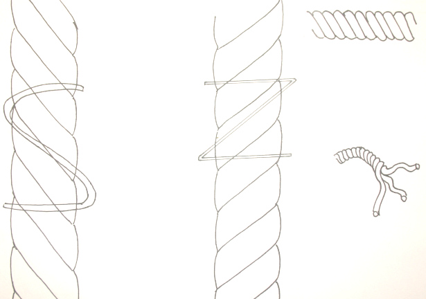
"S Twist" yarn is also called "left twist" or "counter-clockwise
twist" as that is the direction the spindle (or spinning wheel) was turning
when the yarn
was spun. If you look at the cut end of the yarn, however, it will appear
the opposite. Confusing. Similarly, "Z twist" is "right twist" or
"clockwise twist" as that was the direction of the spinning wheel, but if you
look at a cut end, it will appear to be rotating to the left.
In my rather simplistic approach to rope making for ship models,
I refer to "Z twisted" lines as "rope" or "rope-laid", and "S twisted"
lines
as "cables" or "cable laid". For the most part, with a few important
exceptions, on a typical ship of 18th, 19, or 20th century, the
standing rigging will be S twisted and the running rigging will be
Z twisted. The term "cable" probably refered to a more tightly spun and plied
rope regardless of the direction of spin, and the term "hawser was used to refer
to a less tightly spun/plied product. When using these latter terms
it is necessary to specify the direction of twist, as in "cable - left twist"
or "cable - right twist" or "hawser left twist" or hawser right twist".
I find that confusing so just the term rope or Z twist versus cable or
S twist.
I recognize that this usage of "rope" and "cable" differs from that
of others, including recognized authorities, but as I said earlier,
my approach is admittedly simplistic and more an approximation
than a detailed replication of what may have been the original
materials. If one reads the various material available on rope-
making, including some primary source material, the terminology
is sometimes confusing, and ropes were clearly made up in many
different versions depending on their usage. Shrouds, for example,
were generally four-ply cable-plied Z-twisted strands twisted around a
central core of rope. Descriptions of ropes and cables describe up to nine
plies or strands
being used to make them.
Also, as above, the term cable is used to mean rope that is more tightly coiled
or twisted. The term "hawser" is used in similar sense to
refer to a less tightly twisted cordage (rope or
cable twist), which is a looser twist than that of "cable".
Hawser also refers to a particular type of line
either rope or cable laid that is very thick or heavy and used
to moor or tow a ship. In this latter sense, the hawser was
intended to be less tightly twisted so it has more "give" or
flexibility than a tightly spun line would. When using the term
hawser in this sense, it says nothing about the direction of
the twist, and one can have rope laid hawsers or cable laid
hawsers. In the end, after
a lot of research, I concluded that for the purposes of model-
building, a simpler approach would be means to preserve
perspective and sanity and still give a good looking result.
Hence the usage as described above.
With all that said, here is a brief glossary of the terms I
use when discussing rope making.
YARN - a spun, twisted length of cordage made from fibrous material. It is the
fundamental unit of rope. If unraveled or untwisted, it yields the starting
fiber. Yarn may be right, (clockwise), or ("Z") twist or left, (counter-clockwise),
or "S" twist. Yarns are twisted together into "strands". The direction of twist
when combining yarns needs to be in the opposite direction to the direction of
twist in the yarns themselves.
SPUN YARN - term for hand spun threads and thin yarn made aboard ship from
remnants of discarded or worn rope or sailcloth. The rope or cloth was unraveled
by hand down to its component fibres and then hand spun into yarn. Spun yarn
was used for many things aboard a ship, from hand sewing or repairing
sailors' clothing to sail-making and repair. It was also used to lash ropes together
and to wrap around ropes to prevent chafing. It was also used for caulking
seams and cracks in the ship itself. I suspect that the resourceful seamen
made and used drop spindles of various types for making spun yarn, something they
did in their "idle time".
STRAND - a length of cordage made from multiple yarns twisted together. The
"lay" or direction of twist of the strand is opposite that of the yarn. Strands are
then plied together to make the final product, rope.
ROPE - a general term for a length of cordage made by twisting together or
"plying" multiple strands. The strands are twisted together in the opposite
direction to that used to make the strands. Rope as a specific term refers to
a final product of cordage that is right-twisted (clockwise) or "Z-twisted".
I use the term to refer to any final product of rope-making that is Z twisted. In
the general sense the term rope may refer to anything regardless of direction of twist
or tightness of twist or ply or number of strands when
discussing rope making. I find this general use confusing and so restrict the
term rope to mean only the Z twisted final product.
CABLE - in general, any very thick rope and a general term for a tightly
twisted or plied rope. In older terminology, cable laid
cordage is more
tightly twisted than hawser laid cordage and is thus less flexible and less
prone to stretching. Cable in the specific sense that I use it refers to a
final product of
cordage that is left-twisted (counter-clockwise) or S-twisted. Most standing
rigging for sailing ship models of the 18th through 20th century will be
cable-laid, tightly spun and plied with a final product that is S-
twisted (left twist). I use the term cable to mean this S-twisted cordage
regardless of the tightness of twist or number of strands. When making cable-laid
cordage for standing rigging I do spin and ply it tighter than when making
cordage for running rigging, but do not use the term cable to refer to the tighter
twisted material or the term hawser to refer to cordage twisted less tightly. It is
simpler this way, as the term I use is based on the direction of twist of the
final cordage rather than some other characteristic or its intended use.
HAWSER - a general term for a large rope or cable for the purpose of mooring or
towing a ship. The term can also mean a less tightly twisted rope or cable than
a cable-laid equivalent and in this sense it has no meaning as to the direction
of the twist of the final product but implies a less tightly twisted cordage
of either left or right handed twist. Some people refer to rigging cordage as either
cable laid or hawser laid and specify for each the direction of twist. I use
the term cable to refer only to S twisted cordage regardless of size and
prefer the term rope to refer only to Z twisted cordage.
ROPE - in general, a term for a length of cordage made up of multiple yarns
twisted into strands which are then plied together to make the rope. In this sense,
the term does not refer to the direction of twist of the cordage. In the specific
sense that I use, rope refers to cordage in which the final product is plied up
from strands
which are twisted together in right twist (Z twist) to make the rope. The strands
will be themselves left twisted and sometimes made from multiple right-twisted yarns,
as will be discussed later.
LAY - the direction of twist of a plied length of cordage - rope or cable.
S TWIST, Left twist, counter-clockwise twist - a lay in which the product, when
viewed held vertically, has a diagonal groove running from upper left to lower
right. The term "left" or "counter-clockwise" refers to the direction of rotation of
the spinning wheel or spinde at the time the final plying was done.
Z TWIST, Right twist, clockwise twist - a lay in which the product, when viewed
held vertically, has a diagonal groove running from upper right to lower left.
ROPE MACHINE - a device or collection of devices for twisting together multiple yarns
into strands and then twisting (plying) strands into larger diameter cordage. The latter two
steps can be repeated one or more times to create larger and larger cordage. The
resulting product of this twisting and plying is designated in terms that refer
to the direction of the lay in the final result as well as to the tightness of
the twist in the plying and also to specific purposes for which the cordage is
designed.
Cotton rigging materials
There are multiple fibres that can be spun into ropes for use in ship models.
I use cotton at present because I prefer using a natural fiber and fine cotton
threads and yarns suitable for rope-making are readily available.
I used linen for the rigging on the model of the Essex and was
not pleased with the result, as linen is a rugged but brittle fiber, which
can fracture when crimped tightly. This is not a good characteristic
for a model because, for example, when tying
a linen line to an eyebolt the linen may break. Further, lines made from
linen loosen (stretch) when dry and
tighten when damp or wet. These changes are different than with cotton line
and with changing humidity the lines slacken and tighten noticably. This
can work the lines where they are tied or pass through a pulley and make it
more likely they will break sooner rather than later. So I used cotton
threads to make the cordage for Vandalia (and multiple models since) and have
been pleased with the results.
When setting about to make the cordage for a model, I first calculate the
size of the lines likely found on the original, using Steel's Elements as a guide. Since the
size of rope was given as circumferance in old literature, I convert the dimension to
calculated diameter and convert that measurement to thousands of an inch. That way I can
measure the finished line with a micrometer to be sure the diameter is appropiate
and approximates in scale the original.
Steele's charts and tables will also give information at to whether the line
is rope or cable and the number and size of blocks used with the line. Once a
list of needed sizes of rope and cable is prepared, I can get going on making
the cordage.
As an example, below is a listing of the cordage for the model of Vandalia
together with notes on how to make up the cordage from available thread
and yarns. The latter information is derived simply from experimentation.
When I find a new thread or yarn I think might be useful for rope-making,
I use the rope machine to spin some it tightly and measure that single strand.
then, I use multiple strands of the thread to make up three and four ply
versions. If the thread as it comes is rope laid, it will ply up into a
cable laid product and vice versa. For larger material, I may first make
up a three or four ply rope or cable multiple times and then use those to
make up a three or four ply even thicker material. I keep the results of
all these experiments on cards with the make up of each one noted on
the card. I have a box of cable-laid material in many sizes as a reference
to use in planning a model, and a similar collection of rope-laid material,
although not in sizes as large. The only confounding issue is that
manufacturers may discontinue making a particular yarn or thread
from time to time, so I tend to stick to readily available material
from major manufacturers. Thus you will find sewing thread from
Guttermann and crochet yarn from Coats in my stash. I also have a
good supply of fine silk threads, but use them mostly for fine
rigging and for tying off or serving smaller line.
Here's the rigging chart. I prepare one for each model and
keep the information in a big spread sheet since many times I will
use the same sizes of rope and cable in multiple models. And I
usually make extra of every size line and keep all the left over line
when the model is done.
During a visit to the Naval Academy ship model collection in the late 1990s, I had a
chance to visit the model shop and spend time with Bob Sumrall, the director
at the time. Bob showed me the rope machine they used there.
He said they had been experimenting making rope in the shop for a while
without much success
until he went to a county fair and saw some Amish men demonstrating
rope-making. They were
using a large electric motor-driven machine. which had one end with multiple
spindles that spun the strands and an opposite end with a single spindle
that plied the strands into the final rope. Overall it was a rough,
rugged process. Bob said the men even used large wooden mallets to pound
the rope into shape. He came back from the county fair with a different
attitude and approach and in the shop they
buit a copy of the machine he had seen.
It was
a large contraption driven by fractional horse power electric
motors and I shamelessly copied the design for a version of my own.
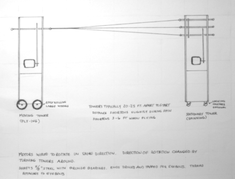
I made up two 4 feet tall
rectangular rolling towers of plywood. I had recently
taken down an old fashioned bench mounted power shaft and had lots of
belts and pulleys and shafts and a motor from that, which I used for the
rope machine. The wood was some 3/4 inch plywood about 12 inches by
48 inches left over from a shelving project plus some 2 x 4 scraps and
wheels scavanged from a discarded lawn mower. All I had to do was
get a few more shafts and cut them to length for the machine's spindles. I
drilled and tapped both ends of these shafts and put eyebolts in the ends.
The layout
of the shafts and pulleys and the drive motors is shown in the first diagram
below. The second diagram shows how the two towers were used when making
rope. By setting up the machine in my garage, I could make lengths of rope
around 20 to 25 feet long.
The actual rope making process takes place in two steps. First the
component cords or "strands" to be made into a "rope" are spun, actually
over-spun, while holding the strands under tension. Then, the spun
strands are twisted together or "plied" by rotating them in the opposite
direction. The excess twist in the over-spun component strands is
relieved by the rotation in the other direction and by the relaxation
of tension when the over spun strands coil about each other.
The design of the machine supports this two stage process and will
be discussed further.
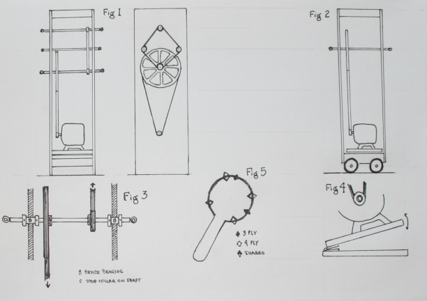
In summary for this first rope machine, there were two towers.
One, the "spinning" tower had 4 shafts spaced equidistant apart running through
bronze bearings in the plywood sides of the tower with an eyebolt in each end of
the shafts.
By placing an eyebole on both ends, the direction of rotation could be
reversed by simply turning the entire tower around rather than reversing
the direction of rotation of the drive motor. In the first step,
when spinning the component strands, the spin is in the same
direction as the existing spin (or twist or "lay") of the stands. In other words, if
you are starting with threads or yarns or strands that are right-twisted,
you must apply the spin with the rope machine in the same direction. If the
strands are Z twist, they should be spun in the right hand direction. And
similarly, if the component strands are S twist, they should be spun left twisted.
Whichever direction the spinning is done, the plying must be done in the
opposite direction to produce a stable product. So if you are starting with
thread that is right hand twist or Z-twist or what I term
"rope" and spin three or four of these threads with the machine, those
spun threads will
have to be plied in the opposite direction and will therefore produce a left handed
or S twist result, or what I term "cable" laid rope. More on this later.
In the original rope machine, the "spinning" tower had four shafts
as described. Inside the plywood tower, each shaft had
a small (one or two inch) pully on it and these four were connected
by a fan belt so they
rotated together. The lowest shaft had a second much larger pully on it
(eight to ten inch
diameter), which was driven by a second
fan belt connected to a one inch pully on a half horsepower electric motor. This tower
was stationary, although in my first version of the machine, I put locking casters
on it. I did this to make turning it around easier, but they were not necessary and
were soon discarded, as the tower was stationary during the rope-making process
and light enough to turn easily without the wheels. The motor was mounted on a
hinged wooden platform to tension the lower belt as in the diagram above.
The second tower was the "ply-ing" tower, which had a
single shaft with eyebolts on each end with a large pulley on it driven by a small
diameter pulley on a second electric motor. The tower
with the single shaft had large wheels on it, about 6 inches in diameter, and it
rolled easily. A little too easily, I found out. I usually had about
15 to 20 pounds of additional weight in the
bottom of the rolling tower to increase the resistance to rolling and
increase the tension in the rope during the spinning and plying process. There
needs to be some resistance to the tower's movement and I found the proper
amount with experience.
Both motors had a hand switch wired into the extension cord into which they were plugged,
allowing
them to be turned on or off easily and quickly when making the cordage.
To make rope, I separated the two towers twenty or more feet in my garage. The rolling
tower moved
easily on a smooth concrete floor. I began by tying threads running from each of three
or four shafts on
the moving tower to the single shaft of the stationary tower. Because the shafts had eyebolts
on both ends, I tied the thread to the side that would produce rotation in the same direction as
the lay of the tread to be use. In other words, when making rope (or cable) the first step is to
produce a hyper twist in the starting cordage. Also, when setting up the machine, I tied the
threads to the appropriate end of the moving tower so that when it was turned on, the
direction of rotation would be in the opposite direction as the existing twist of the
thread and therefore
in the plying step, the cords would ply up in the opposite direction to their original
direction of twist.
This business can be a bit confusing, but remember that the
direction of twist - right or left, clockwise or counter-clockwise - refers to the
direction of rotation of the spindle that made the yarn or rope, not to the direction
of the twist of the material itself. So, if you are starting with a Z-Twist or right-hand
or clockwise twist, when you are looking at the rope machine you want the spinning tower
spindle to be rotating clockwise. And for the same starting material, you want the plying
tower spindle to be rotating counter-clockwise.
Spinning and plying is done in opposite directions because the spinning causes an
over spin or hyper-twist in the strands and they will therefore coil about each other
easily in the plying step to reduce the tension introduced by the over-spin. The
tension created by the over-spin also caused the mobile tower to move during the
spinning process as the spun strands shorten. The tension you apply by restricting
the movement of the tower with weights or other means keeps the over-spun strands
from coiling up on themselves, which they will do if the tension is relieved before
the strands are plied together.
With the threads set up, I turned on the motor in the stationary (spinning) tower and began
the process of hyper twisting the cord. While the thread was spinning, if I wanted
a waxed cord, I waxed the threads liberally with
bees wax, but this was optional. If wanting a heavily waxed cord, I repeated the waxing
multiple times during the process, during the spinning, afterward when resting the
threads, and sometimes when plying. My personal preference is for un-waxed or only slightly
waxed rope, so I rarely use bees was these days.
Spinning will first tighten the twist of the threads or strands and then begin
to over-spin or hyper twist them. I spin for a while, then stop and release the tension
on the threads a little by either pushing the moving tower ahead a little or by
simply pinching one of the strands at two places about a foot apart and moving
my hands together to see if the thread coils up on itself. With a little experience you
will learn just how much overspin or hypertwist is needed. During this step, the threads
will shorten slightly
and the rolling tower will move slightly to accommodate the shortening, but you do
want to be working with some significant tension on the threads to better "set" the
spin and prevent the over-spun strands from coiling up on themselves.
Once the threads are hyper twisted, I pause for a few minutes to rest them and
rub the threads with a pinch, sliding along the full length of each thread. This
is also a time to apply bees wax or more bees wax if desired.
The final step is the ply-ing step in which the spun threads or strands are
twisted together to make a "rope" (or "cable"). As mentioned above, the plying
rotation direction is opposite to the spinning rotation direction. I marked
the towers on each side with arrows indicating the direction of rotation of
the shafts and designated them "R" or "C" to remind myself of the direction
of the twist.
In the plying step, the single spindle of the second tower is what applies
the rotation. I use a device to keep the spun threads separated as they
begin to ply together for two reasons. First, when you first start the rotation
of the plying shaft because it is in the opposite direction in which the
threads were spun, they may relax briefly before starting to ply together.
When they relax, they may sag a bit and get entangled. Remember that you
have over-spun them and they "want" to coil up about themselves or with another
thread. Second, when you start the plying rotation, the plying will be loose
and along the entire length of the threads. I like the lay of the rope I
am making to have a pretty steep angle (tighter twist) and find it much easier
to use a device
to force the plying to begin at one end, the end of the plying tower, and
proceed from there along the entire length of the rope in a controlled fashion.
The easiest way to do this is use something to keep the threads separated
until they enter the actual twist of the growing rope as it plies together.
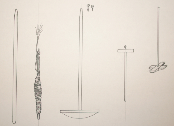
At first, I used a conical shaped wooden "top" with 3 or four
grooves in it, depending on the number of threads in the rope, to keep the threads separate
as I turn on the second machine to begin to ply the twisted threads together. The top
keeps the plying uniform as it moves along the length of the threads. If the machine is set up
properly and the threads are being first twisted and then plied in the proper direction, the
component threads will lay up easily during the plying process. Once the plying has gone as far
as possible and the machine shut off, I simply cut off the ends at the moving end and then at the
stationary end. Again, if the twisting and plying has been done in the proper orientation and to
the proper degree, the newly made rope will barely tend to unravel. There may be some
over twist from the plying process and the new rope may tend to spring back when you
cut if free from one end, so it is best to hold the rope when cutting it free and then
let any over spin work out gradually, releasing it a foot at a time. Once I have the rope off the
machine, I often hang it over a large (2 inch or greater diameter) pipe and let it rest
for a few days
so the fibres relax into the new configuration.
Rope versus Cable and how to get there
If you haven't read the section of rope and the definition of terms I use
when talking about rope and rope-making, it might be a good idea
to revies that section and the definitions here.
When making up the cordage for a particular model, I first decide whether the line I need for
a particular use is to be "rope laid" (Z-twist) or "cable-laid" (S-twist). The terminology
comes from the spinning mill and refers to the direction the slant of the "lay" of the
yarn/thread/rope
appears when looking at it with the yarn held vertically or horizontally. And the name
comes from the slant of the English alphabet letters for which the twist is named.
Saying it yet again,wWhen threads of one lay or twist are plied up into
a larger cord, the lay of the result is opposite the lay or twist of the starting thread.
So if you want what I term a "rope" (Z-Twist) you make it up from "cable"-laid (S-Twist)
component yarns or threads or strands. Use rope to make cable
and cable to make rope, as described above.
When two or three or four threads or strands or yarns of
a given diameter are plied up into a larger cord, the result is not double or triple or quadruple
the starting
diameter, as the stands tighten up during the spinning process and that reduces their
diameter and when they are plied together they nestle up so the resulting diameter
is smaller that one might expect.
This means that much experimentation is needed. Which is what I did to start out. I first
gathered many 100% cotton threads, from machine sewing threads, hand quilting threads, button
and carpet threads, through various cotton crochet and embroidery yarns and measured the
diameters of these as they came from the manufacturer
using a micrometer and making multiple measurements with the yarn relaxed.
I then spun them on the rope machine close to the point of hyper twist (when the thread begins
to coil up upon itself), let them rest a bit and re-measured the diameter. I could then
store these samples on small cardboard rectangles writing notes on the cardboard as to
the name and size of the original material and of the spun material. I record the diameters
in thousands of an inch and calculate the diameters of cordage needed for a model the same way.
This gave me a small reference library of available starting threads or yarns to use.
Once I knew the characteristics of my starting threads the next step was to ply each of them
up into a three ply cord. If the thread were "rope" laid, the result was a "cable", and vice versa.
Once this was done, I measured the diameter and of the plied cord and stored each on a card
with the diameter, the lay, and the source threads recorded on the card.
At this point I could return to my rigging calculation tables made up at the beginning of this
process. A sailing ship would have many, many different sizes of cordage, mostly "rope", but
some "cable", with the rope used mostly for running riggin and the cable for standing rigging.
When deciding what ropes I need to make for a model, I go through the list of the lines of the
prototype and their sizes and direction of twist. Most reference material will record the
size of each line as its circumference, as was the practice at the time. First, convert
the circumference to its diameter then convert the diameter of the original to the scale of the model,
and correlate the needed scale diameter to those samples you have made. Sometimes you may
need to go back and experiment with additional samples on the rope machine. Remember that
you can also make up two, three, or four ply cords if you need to adjust a diameter down or
up a bit. It is always necessary to round up and down a bit when deciding how many
diameters of cord you need to reduce the number of different
sizes of cordage you will need for a model. About ten or 12 different sizes of rope should be
sufficient along with the same number of sizes of cable.
Then, it is back to the rope machine to make up the sizes needed. For larger sizes, particularly
for the standing rigging, there are a couple of approaches. You can first first make up several
smaller strands and then ply
them together to make the larger cordage, as described immediately below. There is a
simpler approach, which is described below this.
For example, when making up material for a main stay or for
shrouds for main or fore mast, you will need a "cable" laid cord of the desired diameter. For
the "Flying Cloud" main and fore stays, I needed a cable of 0.085 inch diameter. I made this up
by starting with a 10/2 cotton weaving yarn which was S-twist as it came off the cone. I first
made up a "rope" of four plies of that yarn - spinning it left twist and plying it right twist.
I did this four times and then used the resulting "ropes" (Z twist) to make the final product
by spinning (right twist) and plying (left twist) four of them into the final cable-laid
result. I did this four times to have extra if needed. Since this was for standing rigging,
which would be tarred, I later dyed the cord black using an alcohol based leather dye.
Fortunately, you don't often need to do all that. I work in 1:64 scale most of the time, so
the ropes I need are larger than if working at 1:96 scale. But even at this larger scale, it
is unusual to need to go to all the work described above as long as you have available
larger diameter starting threads or yarns.
In another example, for the shrouds for the fore and main masts on the "Flying Cloud", I
needed cable that was 0.055 inch diameter. I made this up starting with "Aunt Lydia's Size
3 Crochet Cotton", which is rope laid (Z-twist, right twist) as it comes. Spinning three
strands of this and plying the three together gave me a result that was exactly what I needed.
Note that
when I spun this cotton yarn, I got a single rope-laid strand with a diameter of 0.027 inch,
so when three-plied, this material increased its diameter just about double, not triple. There
is no consistent multiplier I have found to accurately predict the increase in diameter when
increasing the number of plies, as it varies with the starting material, so this is why you
always need to experiment and make up reference samples. And keep them on hand.
Remember also that some of the ropes/cables might be tarred, as the shrouds and stays, so you might
need extra of certain sizes that occur un-tarred and tarred. Also it is necessary to make up a few
special types of cordage. Shrouds, for example are four-ply, cable-laid. Anchor cable is three ply
cable laid, and certain rigging ropes are cable laid (3 ply). And always make extra!
So you can appreciate the process. If you need a three ply "rope laid" rope of a certain diameter, you
have to make it up from three "cable-laid" cords of some diameter less than the resultant rope.
As described above, you may need to do the plying process a couple of times to get the result
you want, but this is uncommon.
It sounds like a tremendous amount of work, but once you have the machines set up it is possible to
make up the cordage for several models in two or three weekends. On a final note, recall that the
length of the resultant cordage, rope or cable, is determined by the distance between the two
towers of the rope machine, which is why the old "rope walks" in sailing days were located in the upper
storeys of long buildings. And why I set up my machines in a garage where I could
get 15 to 25 feet of finished line by putting the towers at the extreme ends of the garage.
If you know the make up of your desired product, how many yarns of what type and size are
needed, you can do the process in a single step. In the example above, making the main
and fore stays, the desired product
is cable laid with a diameter of 0.085 inches and made up of sixteen pieces of the 10-2 cotton
yarn, and the starting yarn is cable-laid. To do the same thing as described above in a
single step, just tie four lengths
of the yarn to each of the four spindles. Then use the "spinning" step to actually ply the
three strands on each spindle together. Note that you will do this step by twisting each group
of three in the opposite direction to their existing twist. So, in this case, you would run
the machine in the right-hand (rope)direction during the "spinning". You are not spinning,
however, you are plying, so that is the reason for the using the opposite twisr.Then, once
these groups of yarn have been tightly
plied, use the machine "plying" step to twist the four groups of four yarns together. This way of
making a rope or cable requires a bit more attention to setting up and twisting the yarns, but
it is a great time saver. It is analagous to the way a traditional ropewalk makes rope.
The key is to know exactly how many yarns are required to yield the
desired size final product.
The rope machine described above was in service for nearly 25 years, and traveled with
us from Oklahoma to Virgina to California to Arkansas to New Mexico and finally to
New Orleans. But I foolishly scrapped it when "downsizing" in 2019. I built a table
top version of the machine, powered by 12 volt geared DC motors,the type used in
radio-controlled paddle wheelers, and using toothed belts and pulleys of the type
used in robotics and certain copy machines. The layout and design of the machine was
much the same, but it was designed to use on a table top. I also added a control
box that contained the transformer and a series of switches so I didn't have to
turn the towers around to change the direction of rotation. And I labeled the
controls clearly to keep mistakes at a minimum. I thought it should
do the same sort of job as the larger version even though it would not make rope
as long as its bigger brother. It was initially limited by the length of our dining room
table (seven feet) but in our last move, we got an apartment with a long hallway,
about fifty feet. I could set it up the new machine easily on two eight foot
folding tables and even separate them for longer length rope, but I had downsized
those tables also. So currently we are still working on the seven foot table.
The total cost of this second machine was well under one hundred dollars as the wood
used was on-hand scrap. The motors, transformer, switches and wires were less than
fifty dollars, and the 1/4 inch brass for shafts, the pulleys, and an assortmet of
drive belts less than fifty. (2020 costs)
Following are some pictures of the "new and improved" version of the
rope machine along with some commentary and samples of rope made on the
device.
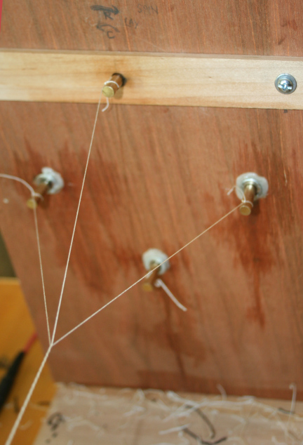
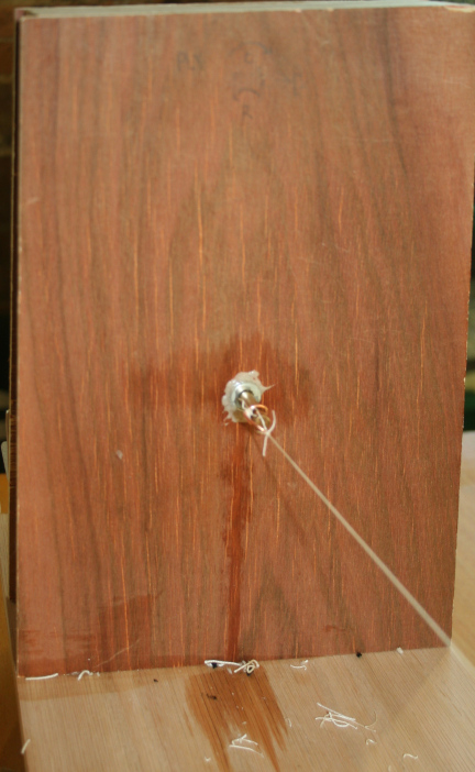
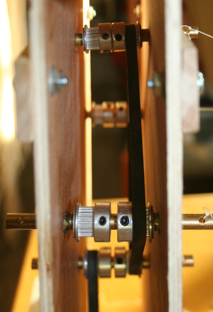
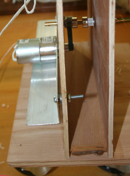
These first two photos show the two mini-towers of the table top rope machine.
The photo on the left shows the stationary "spinning" head, which has four
rotating shafts or spindles and is clamped
to the the table. In this picture, three strands have been spun and plied.
This is what the rope looks like at the completion of the process. The photo
on the right shows the moving mini-tower, the "plying" head. It has a single
rotating shaft or spindle and is mounted on casters. The movement of this
tower is controlled with a simple weight on a length of twine attached to
the back of the tower with the weight hanging over the edge of the table. I
use a one pound metal weight but a better arrangement might be a simple
can on the end of the twine with weight added as water or pebbles or similar so
that the resistance can be adjusted for differing rope making needs. For
practical purposes, my one pound weight works well for pretty much
everything. Note the oil stains on both towers from frequent oiling of the
brass bearings for the rotating spindle shafts. These shafts have holes
drilled in each end so their rotation can be reversed by turning the towers
around, but in this case, that is not needed because of the set up of
the control box as described below.
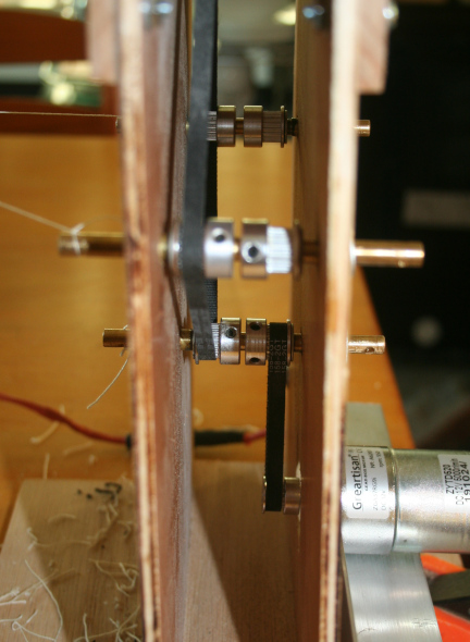
The following pictures show the inner working of the two towers.
As described above, the power is from a geared 12 volt motor designed
for RC steamboat paddle wheel models. These motors rotate at 550 RPM.
In this device, they have a toothed pulley on the drive shaft and it
is connected with a toothed drive belt to another toothe pulley on
a rotating shaft. In the plying head, there is a single rotating shaft.
In the spinning head, there are four spinning shafts with pulleys connected by
a second toothed drive belt so they rotate together at the same speed
and same direction. The first two pictures show the spinning head/tower,
which is stationary.
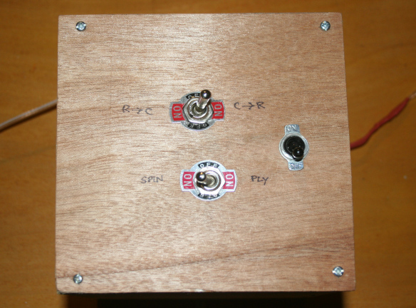
The third picture is of the plying head/tower, which is movable. The
fourth picture shows the control box. The control box contains the
power supply/transformer, which converts 120 VAC to 12 VDC. It is wired
with two double pole double throw switches to permit changing the
direction of rotation of each drive motor rather than reversing rotation
by turning the towers around. It also has a single pole off-on switch. This
arrangement lets me make rope or cable without turning around the towers.
Notice that the controls are labled according to the direction of the
rotation desired. In this case, they are labled according to whether
I am spinning cable (left twist) yarn into rope (right twist) or vice
versa. In the first case, when I set the switch to "C to R", the wiring
sets the rotation of the spinning head to left and the plying head to
right. The second DPDT switch sends power either to the spinning head
or to the plying head when the master off-on switch is turned on. Setting
things up this way pretty much eliminated the thought process during
the actual rope making. All I have to know is the direction of twist
in my starting yarns and set the machine accordingly.
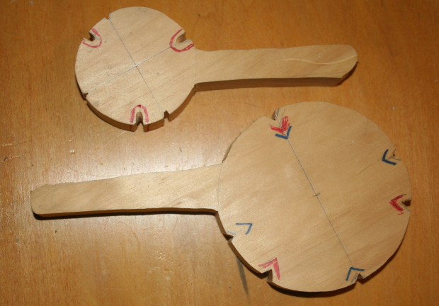
Here's a picture of the Paddles used in the plying step as described
above. One shot shows the two sizes of paddles I have on hand and the
other shows the paddle in use. I notch the paddles for both three and
four ply rope and color code the notches for each type. A little bees
wax in the notches keeps things running smoothly. The larger paddle is
about 4 inches in diameter, the smaller about half that. I rarely use
the larger paddle.
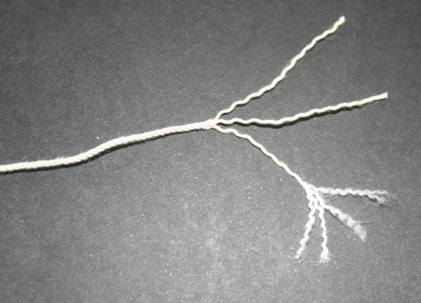
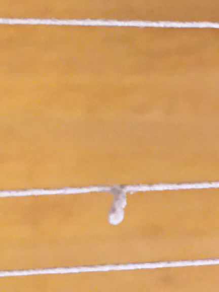
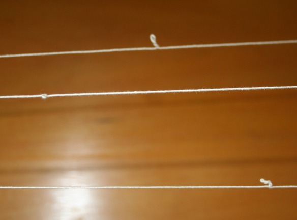
These are pictures of what the yarns look like when properly over-spun.
The hyper twist will result in the yarn coiling up on itself if tension
is released before the yarns are plied. In the first picture, you can
see the yarn coiling up on a single strand. I generally test the over
spin as described above, by piching a single strand in two spots about
a foot apart then moving my
hands together enough to release tension to check for coiling. I keep holding
the yarn firmly as I check it and then pull out the coiling before releasing
my grip. The second picture shows the coiling in all three yarns of a rope
being made, something that happens if you release tension by moving the
plying tower or if you have insufficient weight/resistance on that tower.
When all the yarns coil like this, you need to increase the tension or
spin briefly in the opposite direction to eliminate
the coiling before resuming spinning or proceeding to ply the yarns.
Some final comments on my experiences with this design of rope machine. First,
I would say that the little table top machine does a good job. I have made
a lot of rope with it, from simple spinning to tighten up threads to use for
rigging, to making up larger ropes (cables) for shrouds and stays by making
up three and four ply ropes and then spinning and plying them in three or
four strands into larger cables. It does a good job.
But I will also say that the larger machine did a much better job. Although
it rotated at a much faster speed, with spinning shafts rotation at about
300 - 400 RPM, and it was much heavier, it handled the finest threads
without problem, even fine silks and fine cotton sewing threads. And it
was especially good at making up really heavy cable stock for large stays.
I work mostly at 1:64 scale, so the main stay on a large vessel may
be a cable laid cord with diameter of 0.060 to 0.080 inches. That requires
starting with a cable laid cord, such as a size 10 crochet cotton, spinning
that into a rope laid cord and then taking three or four of the rope laid
cords and making up the final cable laid product. That is a lot of trips
through the rope machine, and working with lengths of 20 feet is much more efficient
than working with lengths of 6 feet.
In addition, the first few inches and the last few inches of any piece of
rope are usually not usable. Sometimes it is just a matter of the component
strands needing a few rotations to settle into the ply-ing in the final step
but mostly is it just the intrinsic wastage of the way the machine is designed
in that the spinning shafts are separated by some distance and that distance
is wasted because it cannot be incorporated into the final rope. So, if
six inches is lost in every piece of rope produced, a twenty foot rope
would lose six inches and the equivalent three lengths of six foot rope would
lose 18 inches.
But in addition I must say that the larger machine was truly easier and better and more
fun to use. To constuct it today and buy all the components would cost
several hundreds of dollars versus a cost for the smaller machine which
would cost less than one hundred dollars. But, if doing it again, I would
spend the extra money. And, of course, have to relocate to a new home with
a garage or a very long hallway. Or leave my rope machine in our present hall
as some sort of industrial decor.
One final note of caution. If you get into rope-making for your models and
if you have, buy, or build your own rope machine, and if you are living with
a fiber person as I do, be prepared for your rope machine to be appropriated
and put to use making ornamental cord for various projects, especially tassels.
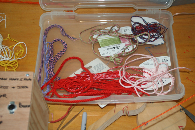
The samples shown are just a few made up from various embroidery and needle work
yarns. They are often very fancy yarns and make up into pretty nice ropes. Perhaps
someday a fantasy ship model rigged with these threads.
I have been making my own blocks for many years. Largely because I did
not like the quality, appearance, and finish of the commercially available
blocks. The situation has changed recently and there are now very fine
blocks available commercially from one supplier, but I still make my own.
On some occasions, I may purchase blocks from a
commercial source and use them as basic stock to re-shape them into something
I find acceptable.
Anatomy of a Block
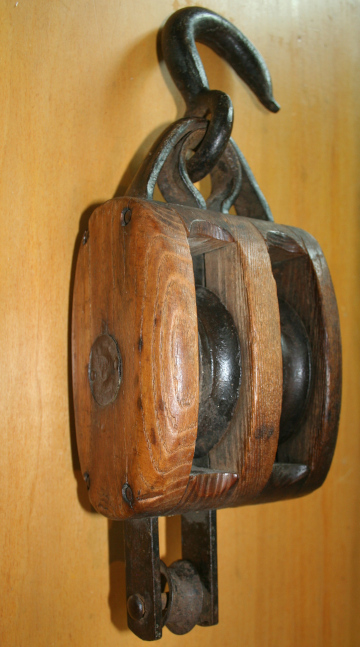
Here are photos of a double block I have hanging by my workbench as
a reminder of what blocks should look like. This one dates from
early in the 20th century and there were likely millions of pulleys
like this in assorted sizes and with one to three (or more) sheaves or
pulley wheels in them. This particular one was probably never used on
a ship but more likely on a farm as I found it in rural New Hampshire.
It has two metal pulley wheels on a metal shaft and there are metal bands
that run between the five wooden parts that make up the shape
of the block. The metal bands extend on one end to make the "eye" that
holds the forged iron hook. On the other end, two of the bands extend
a couple of inches and hold a metal rod with a metal thimble on it,
the attachment point for the rope when the block is part of a tackle.
The block itself measures six inches in length, four inches in width, and
is about four and one half inches across the face. The pulley wheels are
about one inch wide and three and a half inches in diameter. The wooden
pieces are of oak, one and one eighth inch thick at the openings for the wheels
and about three quarters of an inch thick between the wheels and on the
outsides. I figure that this pulley block would have been used with
rope up to about three quarters of an inch in diameter or about two
to two and a half inches in circumferance.
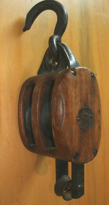
This particular pulley block is about a century later than most of
the models I make, but still makes a good reminder of what a wooden
covered pulley block would look like. Prior to the use of internal
metal bands for the "strop" of the block, the wood sheathing would
have notches at the "corners" to secure the rope used to strop it.
"Strop", by the way, is a term for a short length of rope spliced
into a circle and refers to the way wooden blocks were originally
fastened to ropes or structures on a ship. The circular strop would
be cinched together at one or both ends of the block and a second
rope passed through the small opening(s) thus formed, often and
opening reinforced with a wooden, later metal, thimble, and in time
often by way of a hook. When modeling small blocks I do not strop
them before fastening them to another line or to a stay or to a yard
but tie them with short lengths of fine thread for the attachment
as will be shown in the photos later. For larger blocks, I do strop
them and usually reinforce the stropping with glue to make the
thimble end(s) although rarely I do incorporate a thimble.
Steele's Elements is a good source for illustrations
of various blocks of the day and how they were incorporated into
rigging. And many other of the books listed in the bibliography
have illustrations as well.
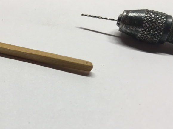
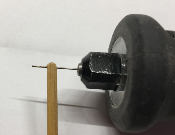
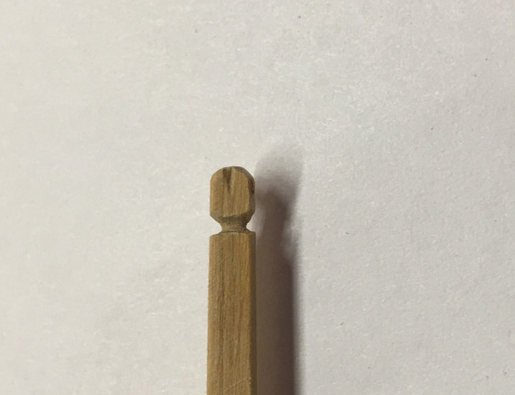
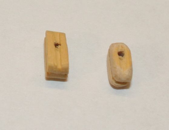
Here are photos of how I make blocks. These show the making of
a small (3/32 inch) block of boxwood but the process of making larger size blocks
as well as double and triple blocks is similar. Although easier for
the larger sizes.
I use boxwood and hard maple for block-making and keep a lot of
pre-cut lengths of wood cut to sizes needed. The maple is nearly as
good as boxwood and has a bit more grain showing and the two woods are
enough dis-similar that I generally stick to one type for most or
all of the blocks on a particular model.
The steps in the process shown below are:
1. Use a fine file and an emery board to final sand the blank to size and
round the end.
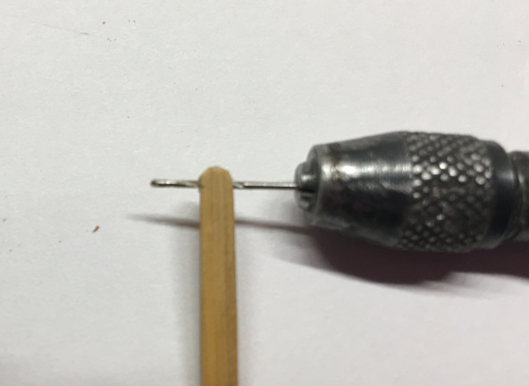
2. Use a pinvise with a #70 - #75 drill to make a starting hole on the face of the blank.
3. Drill a pilot hole with a #77 or #78 drill in a hand held power drill.
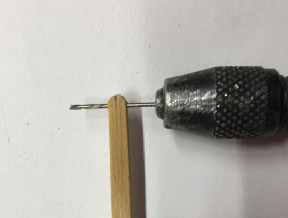
4. Enlarge the pilot hole with the drill in the pin vise.
5. Turn the blank on the side and use a #11 blade and/or a fine triangular file to
notch the upper end of the block.
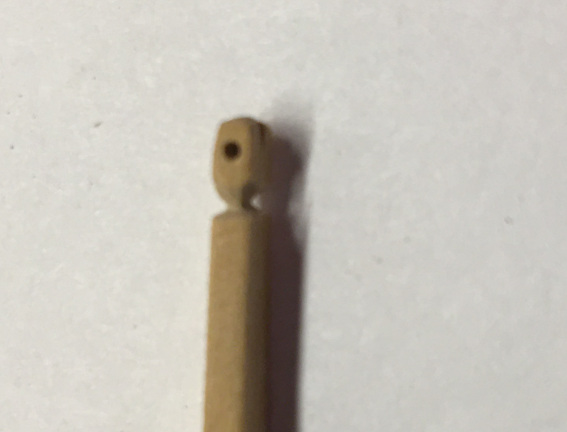
6. With the blade and the file, cut deep notches in the blank where the bottom end of the
block will be.
7. Use the tip of the blade to cut out grooves for the rope extending from the
drill hole to the bottom of the block.
8. Cut the block free from the blank and place it on a spare (dull) drill in a pin vise
to cut notches on the bottom of the block.
9. With the block on the pin vise drill, tie off the "stropping" and stow for later use.
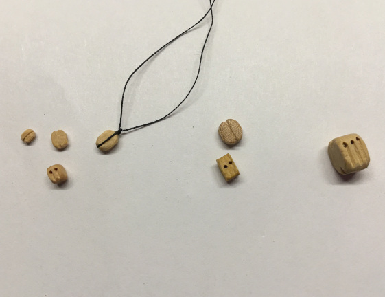
The final photos show a completed 3/32 inch block and the same block after
"stropping" with sewing thread. Last is a photo of various size blocks from
my stockpile; 1/16, 3/32, (single and double) 1/8, 5/32, and 1/4 inch sizes
corresponding to 4 inch, six inch, eight inch, ten inch and fourteen inch blocks
at 1:64 scale.
I sometimes re-work or re-shape commercial blocks to make their appearance more
suitable. When doing this, I usually work with the larger sizes (3/16 or 1/4 inch) in
boxwood if available. Here's a photo of a quarter inch boxwood commercial single
block reshaped.
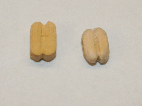
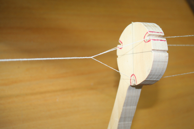
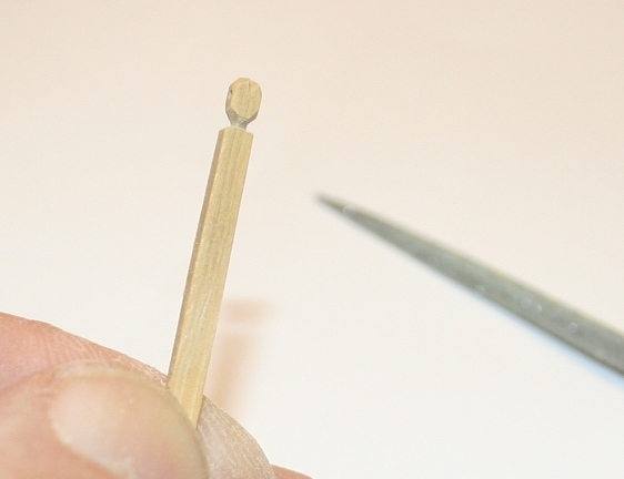
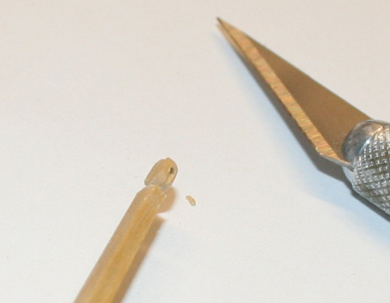
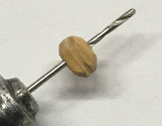
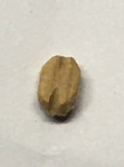
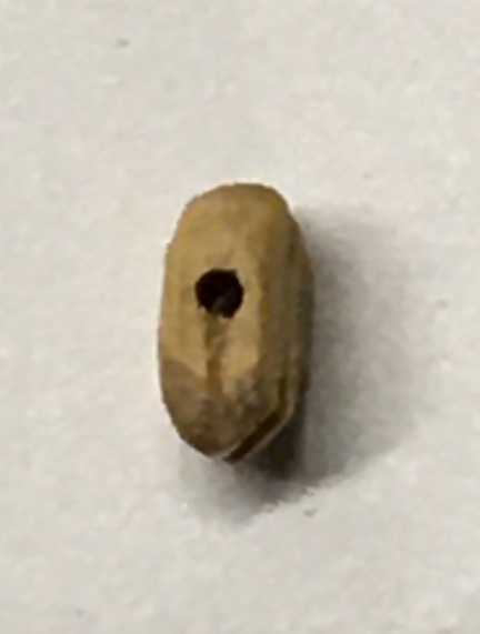
I also make my deadeyes. I make them of lignum vitae wood. First, I turn a
spindle with multiple grooves alternating a shallow groove with a deeper one
in the desired diameter for the deadeye. Then I use a fine saw to cut the deadeyes
apart at the deeper grooves, sand the two faces smooth with fine emery paper and
drill the three holes in each.
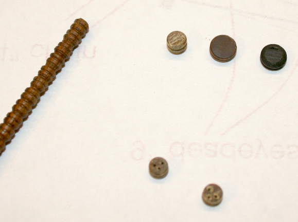
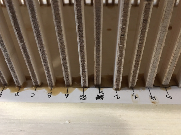
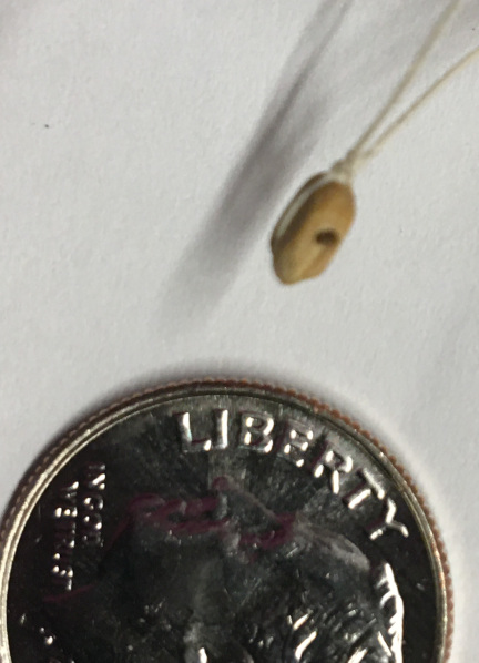
The photo below shows items from the stages in this process. The turned spindle
shown is 9/64 inch diameter to make a scale 9 inch deadeye. The photo shows
one of the deadeyes cut free and also two larger diameter deadeyes afte sanding.
Below are two deadeyes with the three holes drilled.
For practical purposes, this is as small as I go making deadeyes. It is difficult
to get the hole drilled in smaller sizes, so if I need any smaller deadeyes, I
buy them.
When making deadeyes, one must remember that they are thick. Thicker than you
might think. Underhill (Volume 2, page 268) has an excellent discussion
of this and points out that the thickness of the deadeye is related to the
diameter that the lanyard needs to make the bend without losing strength.
In the example shown below, a scale 9 inch deadeye would be 5.5 inches thick, or
just over half the diameter. Similarly, a 12 inch deadeye should be 7 inches
thick. Something to keep in mind when making or buying deadeyes.